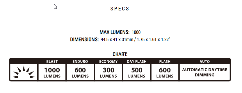
The light that came with my eBike was meh at best. It’s a Lezyne Mini STVZO E65. It’s a single mode 210 lumen light. It does OK at night but at the speeds I ride at it wasn’t cutting it. It also doesn’t flash or have any other settings. I wanted a brighter light, that had a daytime flashing mode and settled on the Lezyne Macro Drive 1000. It is a 1000 lumen (max) light with multiple modes shown in the picture below. It even has an auto brightness setting which is pretty cool. The install was ok, hardest part is getting the wire tray above the battery to hold the wires in tightly so the battery seats in correctly, took me a while to figure out why it wasn’t seating properly and if you do this, that should bring the Pain In The Ass (PITA) factor down a star or two.
The Amazon links in this article are affiliate links, if you choose to use them I appreciate it. No annoying popups here or anything like that. Just the Amazon links that give me pennies on the dollar to help pay for the hosting of this site.
Update 3/28/22
Well I did it, I got the light working great with no rear light dimming and got the full 1000 lumens in max mode. It was sort of a PITA though to be honest. I ended going the relay to a buck converter route. My original plan was to hide the relay and the buck converter down towards the bottom of the frame but there are a lot of wires in there and just not enough room. I ended up putting them on the top of the battery cutout, above the upper battery bracket near the stem. There is a good amount of room up there. Look below at the instructions for the new steps. I’m going to keep the old instructions if you’re changing your light to something within the Dosts/Bafangs specs which would be something like .5A draw at 6v. There is not much out there that will give you more than 300-400 lumens with that available power.
Important! Read this at a minimum before proceeding
If you have a light you want to use with the stock light output it MUST operate at 6V @ no more than 1A. Anymore you risk frying your controller light output (or worse.) Options are fairly limited, and you’ll be hard pressed to find a light with more than 300-400 lumens. If this is what you want to do, follow the Basic Light Swap instructions below.
If you want to install a higher power light 6V+ @ more than 1A you will need to follow the High Power Light Swap instructions below.
Basic Light Swap
| Technical Skill: |  (2 / 5) (2 / 5) |
| Cost: | (2 / 5) |
| Time commitment: | (2 / 5) |
| PITA factor: | (2 / 5) |
High Power Light Swap
| Technical Skill: |  (4.0 / 5) (4.0 / 5) |
| Cost: |  (3.0 / 5) (3.0 / 5) |
| Time commitment: | (4.0 / 5) |
| PITA factor: | (4.0 / 5) |
Preparation (basic light swap)
Make sure you have the tools for the job, not much needed here outside of your standard bike tools (aka Allen wrenches) other than a set of Torx drivers to remove the battery lock. You could probably pull it off without removing the battery lock but getting it out of the way makes for a much easier time.
- A light that supports 6V at .5A
- Set of Metric allen keys
- Torx driver set (if you remove the battery lock) I’ve used these for years on my car, no issues at all
- Phillips head Screwdriver
- Something to cut zip ties
- I use these Hako wire snips, 5 years and still working like new
- Zip ties
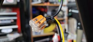
- WAGO lever nuts (quickest) or a soldering setup (bestest) or some sort of crimp connectors (least preferred)
Preparation (high power light swap)
These components worked for me, packaging this all within the frame so the bike still looks stock is a challenge. I tried a couple other DC/DC converters before finding the below which was the smallest I could find.
In addition to the above preparation list you will need:
- A small DC/DC relay that is capable how handling 48V, most range from the 30V’s to 60V’s and have the ability to handle the current (Amperage) of your light which usually isn’t an issue.
- I used this Opto 22 American made Solid State Relay as it’s directly connected to the battery and wanted to make sure it was high quality
- An inline fuse, I don’t like this one TBH, the fuses ARE NOT labeled so you’re kind of hoping they didn’t shift around during shipping. If you drop, forget it.
- I used a 3A fuse on my setup as the light will pull up to 1.5A, I’m really just looking to save the battery if there is some sort of short
- A small DC/DC converter aka buck converter to take the 48V from the battery down to your lights voltage, my light is a 12V so I purchased this one
- Various length’s of 16-18 gauge stranded copper wire
- Adhesive backed Velcro
- Liquid Tape for waterproofing
- I love this stuff, I use it extensively on my Pixel Christmas show and it works great. Not only does it form a waterproof barrier, it’s easy to remove if you need to. It peels off like sticky rubber. Highly recommend trying it.
- Patience
Steps (basic light swap)
- If you have a workstand put your bike in there and remove the front wheel and battery. It’s doable without removing the front wheel but with my t-handle Torx drivers I had to remove it, made it way easier.
- Remove your old light by unscrewing it, cut the zip ties holding the wire bundle together all the way back to where it goes into the frame, disconnect the quick connect.
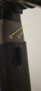
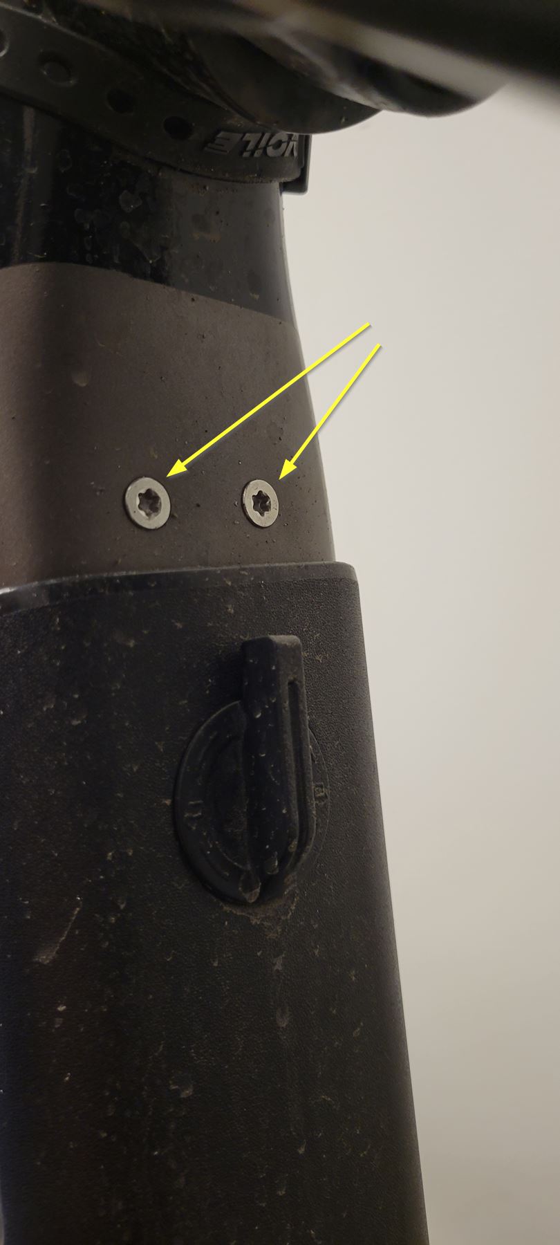
- Somewhat optional: Remove the battery lock from the frame by removing the two Torx screws shown below and twist the key portion slightly to pull out the lock

- Push the new lights bare conductors through the wire grommet and pull out most of the slack so you have room to work with it.

- This light ships with an unterminated end, it is just 2 bare wires. A red (+) and a black (-) I chose to cut the quick connector off the old light, strip away the insulation on the larger wire and then the insulation on two smaller conductors. I then used a couple of 2 conductor WAGO’s to connect the new lights bare conductor to the old lights quick connect as seen below. The old light has a yellow positive wire.

I chose to use WAGO’s, you could solder this, use crimps, etc… Just don’t black tape it, please. - Move the now bonded wires over to the side and remove the silver wire holder thing above where the battery mounts. There are 2 Phillip’s head screws holding it on.
- Now for the PITA part, you’ll notice there are already 3 cables under the silver cover thing. One of them is quite thick and needs to situated in a way that the silver wire cover sit flush with the frame when tightened down on both sides. There is a large connector on the aforementioned thick cable that needs to NOT be under the silver cover or else it will not sit flush. (You’re welcome, I just saved you 20 minutes of putting the cover on, realizing the battery doesn’t seat, taking the cover off, moving around wires, trying again, swearing, slamming, etc…)The new light comes with a generous length power cable, way more than is needed for this install. If you were so inclined you could remove the motor and wire it straight into the motor but I wasn’t willing to go that far. You could also cut the provided cable down quite a bit to make it fit much easier under the wire tray. I choose not to do either and instead fought that damn thing.I ended up using a little bit of gaffers tape to keep my new light wire bundle together enough to be able to stuff it under the cover and tighten it down.You will know if the wire cover isn’t flush if the battery does not seat into the battery lock easily like it did before you started messing with it. 🙂


- Reinstall the battery lock the same way you removed it.

Steps (high power light swap)
WARNING! This involves some moderate voltage with a huge current potential. I don’t suggest you try this unless you are comfortable with basic electronics and knowing what and how a batteries power works and how it can hurt you.
- You’ll definitely want a work stand for this, mount your bike in the work stand, remove the battery and the front wheel
- Remove the wire cover in the battery bay by removing the 2 phillips head screws
- Snip the zip ties off the bottom wire bundle (under the crank) and remove the mesh sleeve
- Remove the top and bottom battery holder bracket things using your Torx driver
- The bottom one can just lightly dangle there for a minute while you do the next step, it will have wires attached
- (Optional) Grab a couple different colored sharpies and draw lines across both sides of the connectors so you know which one goes where when it’s re-assembly time. It’s not difficult to figure out which is which is you skip this step but it might save you some time. Dost did a good job labelling the battery balancer.
- Unplug the wires seen below, there are 2 going into the bottom frame tube’s 2nd’ary battery port, 2 going into the now removed lower battery bracket thing and 2 going to the motor itself. You’ll also see a very thin gauge bundle of wires, this is the light wire that we will use later as well.

- Grasp the battery balancer by the side and pull it off the frame. If you’re lucky the velcro will separate but if not no big deal. It needs to be moved further back later for more wire clearance anyways, store it aside for a bit.

- This is where your comfort in electronics comes into place. I’ll just share how I did mine, by no means is it the best way, the right way, etc… I’m fairly confident in my setup (ran it by a few friends as well) but here’s your moment to shine and have fun with your wiring and electronic know how.
- On the lower battery bracket (where 2 leads are coming out), I cut the attached leads a little more than 1/2 way down so I would have some wire to strip and put into a 3 PIN WAGO. I then attached the freshly cut and stripped leads, the original connectors, and about 3 feet of new 18 gauge wire into the WAGO. (See below)

- I used a zip ties to snug the 3 wires together right above where they go into the WAGO to provide some sort of strain relief (I think)
- I then filled the above WAGO’s with liquid tape, let it dry (mostly, I’m impatient) and zip tied it to the bottom battery bracket thing

Mmm, liquid tape 
Nice and tidy but messy because I want instant gratification - Reconnect the now 6 leads (3+ and 3-) to the lower battery bracket and test fitted it. You can pull out any extra wire length on the wire bundle below the crank to temporarily make more room. Before attaching your velcro to the battery balancer, test fit it. The battery balancer will need to sit back a bit further than the stock location.
- Neatly route 3 cables, your 2 new leads coming from the lower battery bracket and the black and yellow light wire up where the wire tray is above the battery. I just used some gaffers tape to hold them in place

Nice and neat - Having never used a solid state relay, this part confused me like crazy. Thank god for a friend that is well versed in this stuff.
- Terminal 2 is your new ground wire coming from the battery bracket thing
- Terminal 1+ is the “same” wire but split. The relay completes this connection to provide power to the buck converter. So wire this terminal to the ground input on the buck converter
- Terminal +3 & 4 is your positive and negative light output wire from the motor, just make sure you wire the yellow wire to the positive
- Basically what’s happening is, you turn the light on your keypad, it turns on the light output on the yellow and black wire which tells the relay to complete the circuit on terminals 1 & 2

- Wire up your buck converter as seen in the picture below

- Important! The new Positive wire coming from the battery bracket thing goes directly into your buck converter but MAKE SURE IT’S FUSED as shown in step 9 above!
- Insulate your relay as well as you can. I used liquid tape to start over the terminals, waited for them to dry and then covered the 4 relay terminals with electrical tape. Like multiple layers to really make sure it stays insulated against potentially the bare metal frame. This is important!
- I ziptied the buck converter and the relay together and put another few layers of electrical tape over them to be triple sure it would never short against the frame
- I used some liquid tape to waterproof the WAGO I used up top as there is an area for water to ingress. I used a 3ml Pipette to suck up some liquid tape and inject into the WAGO pins, I also slathered some liquid tape over the levers as water can get in that way as well. I also I did zip tie a “strain relief” sort of thing.
Zip tie strain relief 
Waterproof the WAGO 
- When I first wrote this I did not waterproof the WAGO’s in step 19 above, but learned after a rain storm ride, water can get in. It’s not much but I also waterproofed the little rubber grommets on each side of the upper frame tube with some Sugro


- I just pushed the wires up towards the stem, and reinstalled the top battery bracket, having so much tape and wire up there kind of created a cushion for the relay/buck converter to get stuck in. I am going to revisit this at some point soon as I don’t like the whole stuff it and forget it method. I’m confident it would be fine the way it is but just don’t like it like that.
- Reinstall the wire cover above the battery and test it out. I did do a bunch of very sketchy testing before doing this. Like battery half seated, holding it up with one hand with wires sticking out of the sides and testing the light type stuff FWIW.

- Hopefully there’s no magic smoke and you now have a full power 12V light!


Light Mounting
Another cool thing about this light is the ability to mount it directly to your Stem. The included parts worked perfectly with the stem on the bike. The included directions also do a good job detailing the install so I’ll skip over that part. Click here for a PDF of them direct from Lezyne.
Only thing I would add is to make sure your wires are routed nicely in the wire loam/wrap on the outside of the bike going from wherever/however you mount it, into the grommet on the side.
So step 9 would be figure out how and where you are going to mount it, snip the zipties holding the wire wrap together, roughly and nicely route your new cable through them
Step 10, mount the light and make sure it’s loose enough to rotate the handle bars, full compression/extension on the front fork if you mount it there, etc…
I chose to mount mine on the stem as I only run a front fender when there is rain, the mode toggle button is easy to access up there, and I think it looks really neat and clean.


Older References:
Update 03/21/22
So something I didn’t think of that was brought to my attention on the Dost Bike Owners Facebook group is the fact that the light output on the Bafang controller is pretty weak. I’m having a hard time finding the exact specifications but from what I gather it is only a 6V, 0.5A output. That really sucks. I don’t think it’s any fault of Dost but more on Bafangs side. I’ve used the light on the highest setting for about 30 minutes straight so far and didn’t notice any ill affects but in testing last night, I noticed it sucks most of the power out of the rear light making it very dim and making it flash. The flashing part could actually be a positive but I am concerned I will blow the controller up or at least the light output on the controller. It can handle the “Economy” setting above just fine but on the “Blast” and “Enduro” setting, it affects the tail light. In the “Day flash” and “Flash” setting it dim’s the rear light when the headlight is flashing which like I said above is kind of a cool thing. My main concern is harming Bafang’s controller.
That all being said, if you’re looking at this and thinking of changing your light, HOLD OFF FOR NOW.
My current thought it to use the 6V headlight signal to flip a relay (directly connected into the battery) then to a DC to DC converter to power the lights. In my limited electronics knowledge I think that should work but getting it in a package small enough to fit in the frame might be the biggest challenge. Also checking on that with my friends.
Click below for the email from Dost regarding this to another member.
Very, very, nice Jason! I would love to have this done to my bike, but I’m not knowledgeable about electronics. I wish DŌST would supply their bikes with this mod.
I’m thinking they might eventually. My sense from the Facebook group is that a lot of people are looking for better lighting options. I don’t think it would add much more cost or labor to the manufacturing of the bike. Here’s to hoping they do.